1.INSTALLATION
1.1.Be sure to read and understand this manual before installation and use of our gearboxes. All personnel working with this gearbox must be familiar with the instructions in this manual and observe the instructions given. Safety instructions must be observed to avoid personal injury or property damage.
1.2.Installation, commissioning, operation, and maintenance must be carried out by qualified personnel authorized by the end user. The end user must provide a safe operating environment and the necessary protective equipment to the operator. The operator have to read and understand the manual. Moreover, the operator must know and observe officially recognized rules regarding occupational health and safety.
NB. Work performed in specific environment, such as flammable and explosive and corrosion and high and low temperature, is subject to special regulations which have to be observed. The end user is responsible for respect and control of these regulations, standards, and laws.
1.3.Installation
1.3.1.Before installation, please carefully check the list of materials and the information of gearbox installed.
1.3.2.The gearbox is standard delivered in the closed position, limit screws are locked.
 |
 |
 |
|
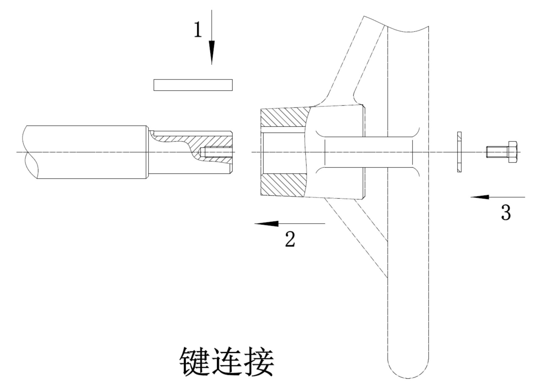
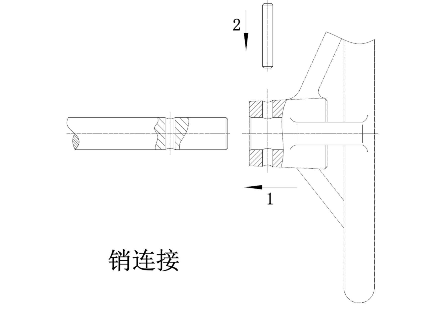
Pin connection |
Key connection |
Square hole connection |
1.3.3.It is recommended to mount the hand wheel on the input shaft (as figure show above) before assembling the gearbox to the valve.
1.3.4.Check if the gearbox flange matches the valve flange.
1.3.5.Check if the valve shaft mounting holes on the gearbox match the valve shaft dimensions.
1.3.6.Check if the valve is in the closed position. If not, close the valve before continuing.
1.3.7.After check all above process, if the flange connection is connected with double bolts, it is recommended to insert the stud bolts into the bottom flange hole of the gearbox as first step.
1.3.8.In order to prevent water or other impurities from entering and damaging the stem, it is recommended to use a gasket for sealing between the flange of the gearbox and the valve flange.
1.3.9.Gearboxes are delivered with eyebolts. Eyebolts should only be used to lift the gearbox. The input shaft or hand wheel cannot be used for lifting the gearbox. Do not lift the gearbox with eyebolts when it is assembled to the valve, input shaft or hand wheel. The manufacturer is not responsible for any damage and safety issue caused by incorrect use of the eyebolt.
1.4.COMMISSIONING
1.4.1.After the installing the gearbox on the valve, turn the hand wheel clockwise to close the valve completely (The valve position is indicated by the position indicator on the gearbox).
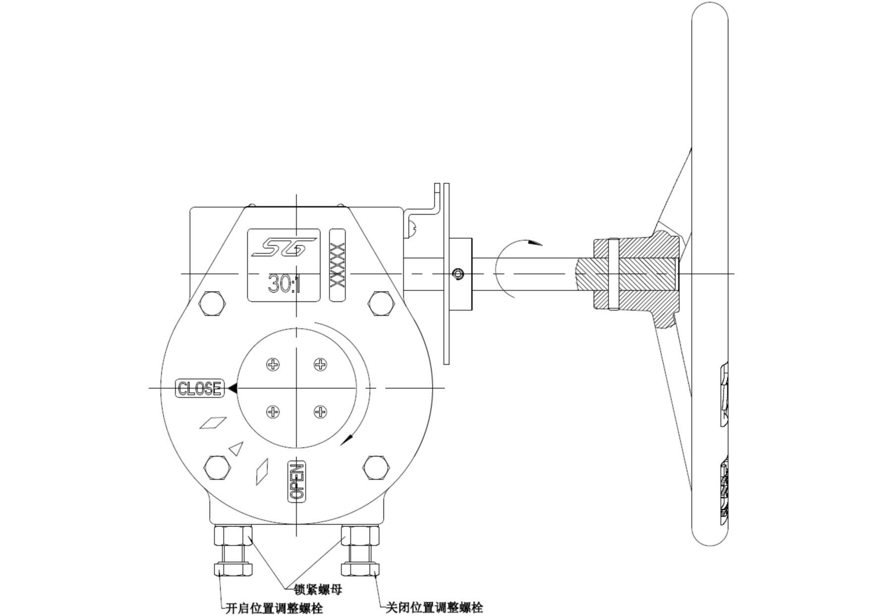
1.4.2.Observe the actual closing position of the valve; if it is not completely closed, turn the retaining screw anticlockwise (release the lock nut), at the same time turn the hand wheel clockwise until the valve is fully closed.
1.4.3.After commissioning, tighten the setscrews clockwise and lock it with the locking screw (locking nut).
1.4.4.Turn the hand wheel anticlockwise to rotate the valve 90 ° to fully open position.
1.4.5.If the valve cannot be fully opened, follow the steps of 4.4.2 and 4.4.3 again.
1.4.6.After above steps are completed, repeat on/off action to confirm the position several times. The commissioning is completed.
NB. Gearbox can be adjusted according to the valve ± 5 °.

Figure 8: Adjusting bolts position
2. OPERATION
2.1.This manual is only appropriate for the quarter turn gearbox.
2.2.The parameters of the gearbox (input / output / turns / material) are shown in Table 1, 2 and 3.
2.3.The position indication of the valve is indicated by the position indicator on the gearbox.
2.4.Turn the hand wheel clockwise to close the valve and turn the valve anticlockwise to open the valve.
2.5.Be sure not to exceed the rated torque given by the parameters of the gearbox (see Table 1, 2 and 3) and only manual operation allowed. It is strictly forbidden to use illegal operating tools, such as torsion bar. The manufacturer does not be held liable for any consequential damage. Such risk lies entirely with the user.
2.6.The gearbox drive mechanism include self-locking function and does not require additional fasteners to hold the valve position.
Post time: Jan-30-2023


